10+ bgp network diagram
Web Network Diagram. Refer to Cisco Technical Tips Conventions for more information on document conventions.

2 Service Provider Mpls Network On 2 Cpe Active Active Ip Mpls Com
R101show ip bgp.
. The connectivity establishment is straightforward. BFD is a feature of BGP that applies to both public and private transit virtual interfaces. The show ip bgp summary command on Router R1-AGS shows the session is active.
Pairs 2 3 are used for normal 10100Mbit networks while Pairs 1 4 are reserved. To extend your existing infrastructure into a virtual cloud network VCN in Oracle Cloud Infrastructure for example to implement a. Peering is settlement-free also known as bill-and-keep or sender keeps all meaning that neither party pays the other in association with the exchange of traffic.
Web RFC 7938 BGP Routing in Data Centers August 2016 Choosing a L3-only design greatly simplifies the network facilitating the meeting of REQ1 and REQ2 and has widespread adoption in networks where large Layer 2 adjacency and larger size Layer 3 subnets are not as critical compared to network scalability and stability. In the diagram shown R101 learns prefix 10130130024 from R103 through iBGP and is unable to announce it to eBGP peer R102. If the active NVA became unavailable the standby NVA would call the Azure API to remap the public IP address and the spoke User-Defined Routes to.
Application providers and. The diagram below illustrates a high level network topology connecting two different Autonomous Systems eg two ISPs namely AS 1206 and AS 1210. UTP CAT5 5e 6 cable is the most common type of UTP around the world.
Web The following diagram shows a high-level overview of how AWS Direct Connect interfaces with your network. Use this network diagram as an example for the first three causes. Use the various telephony devices.
Web In computer networking peering is a voluntary interconnection of administratively separate Internet networks for the purpose of exchanging traffic between the down-stream users of each network. Web As you can see in the picture above the 4 pairs are labeled. This results in two network routes paths toward Azure from the.
Web When you set up FastConnect virtual circuits you can choose to use private peering or public peeringThe details vary depending on whether you are using a FastConnect partner a third-party provider or colocation. Web The diagram shows a network within the on-premises network connected to the Azure hub VPN gateway over ExpressRoute private peering. Web The diagram below shows how an Azure Public IP address is associated to the active NVA NVA1 and the User-Defined Routes in the spokes have the active NVAs IP address as next hop 100037.
Its flexible easy to install and very reliable when wired properly. Optional You can configure Bidirectional Forwarding Detection BFD on your network. Lifecycle of subnet routes.
Configure Call Manager Express TM on a 2811 router. The Neighbor Statement Is Incorrect. Web Tutorial description.
Web R101show run begin bgp router bgp 1 network 17216100 mask 2552552550. Web For example if a subnet or peering subnet route exists for the 10701024 destination and one or more Cloud Routers in the VPC network receive the 10701025 prefix via BGP Google Cloud uses the subnet or peering subnet route and ignores the conflicting custom dynamic route. Web There is also another flavor of BGP which is Internal BGP iBGP and runs between routers in the same Autonomous System eg between the routers of the same ISP or enterprise network.
This tutorial is designed to help you to configure the voice over ip voip features available in Packet Tracer 811. Are advertised via both the ExpressRoute private peering BGP and the VPN BGP. In Gigabit Ethernet all 4 pairs are used.
It will show you the steps required to. AWS Direct Connect components. Check to see if the route is in the BGP routing table.
2
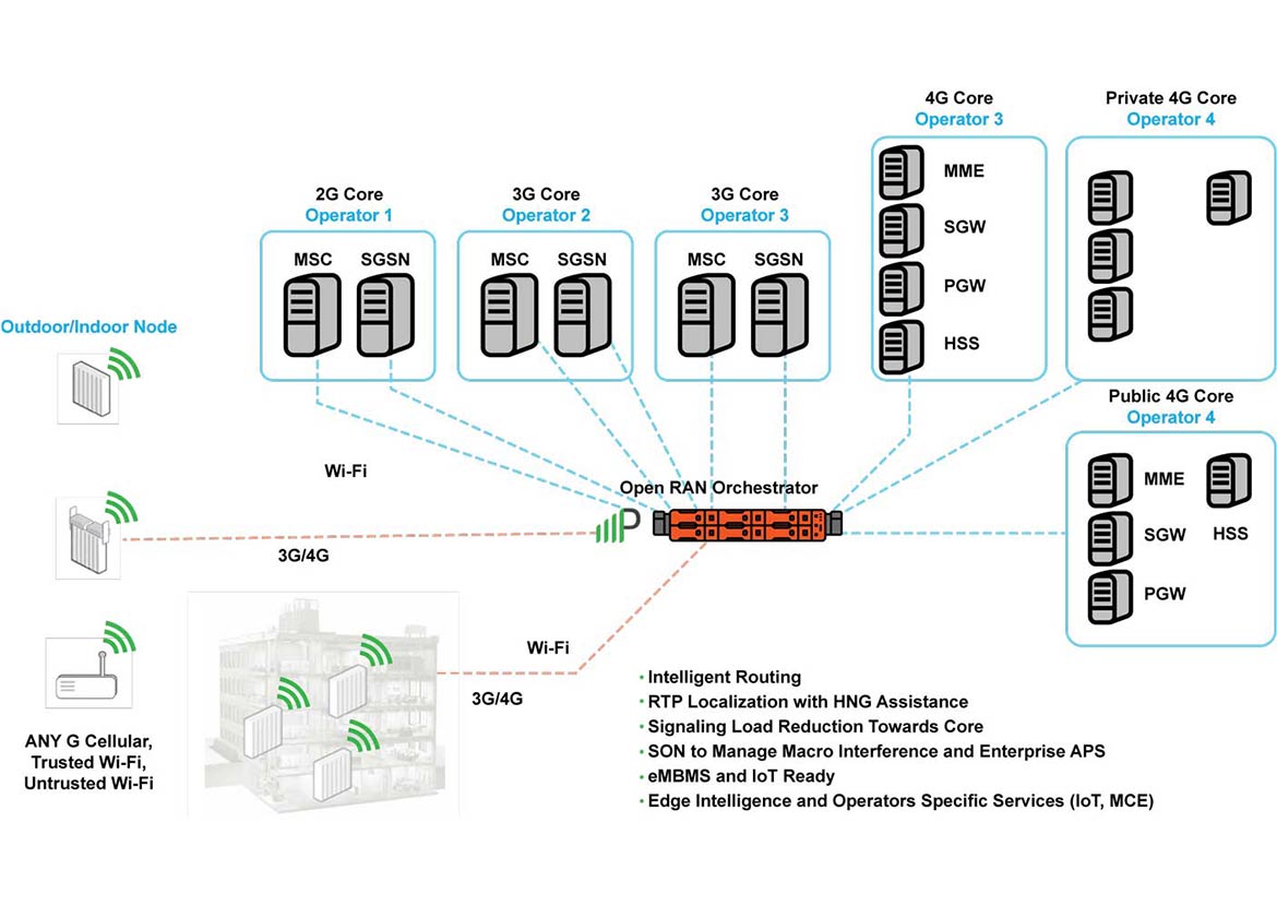
Multi Operator Core Networks Mocn Parallel Wireless

2 5 Years Later The Network Diagram R Homelab

2 Service Provider Mpls Network On Single Cpe Active Active Ip Mpls Com
2

Mpls Layer 3 Overview Mbgp Configuration And Vrf Configuration Reviewed And How It All Works Together The Devnet Grind

Mitel Clearspan Topology Networking Cisco Networking

Internet Sharing On Mpls Network With L3 Switch Ip Mpls Com

Ospf Topology Database Design Optimization Principle Of Isp Igp Routing Apnic Blog

Voice And Video On Mpls Network Ip Mpls Com

Bgp Essentials The Protocol That Makes The Internet Work Cisco Networking Computer Network Bgp

Types Of Routing Protocols Networking Infographic Ccna Cisco Networking Technology

Mpls Network Mesh Topology Dc Dr Setup Ip Mpls Com

Proxmox Ceph Full Mesh Hci Cluster W Dynamic Routing Packet Pushers

Redistributing Internal Bgp Ibgp Into An Igp Why Is It Dangerous Cisco Networking Bgp Computer Technology
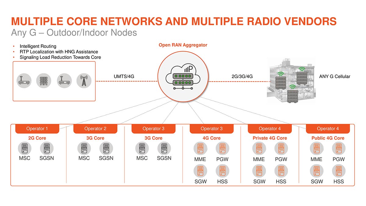
Multi Operator Core Networks Mocn Parallel Wireless

What Is Ccna Routing And Switching Redes De Computadores Mudancas Informatica